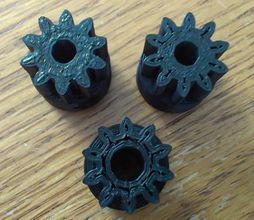
This Christmas season I put my printers to work making unique presents for my family. Everyone with a workshop or a garage got a custom geared light switch cover.
Designing this toy definitely took a few tries to get the desired effect. While doing so I collected notes on perfecting printed gears and I thought it was interesting so I’ve shared it here.
This article is intended as a general guide for designing & printing FDM 3D printed plastic gears.


Geared Light Switch Cover Free Printable STL Files Here.
FDM Printing Specific Benefits & Examples of Gear Use:
So why choose to 3D print gears over alternative manufacturing methods, and what strengths does 3D printing offer?
Printed plastic gears are a cheap, quick, and customizable motion transfer solution compared to alternative ways to make gears. Complexity & 3D variations are free. The prototyping & creation process is quick & clean. Best of all, 3D Printers are common enough that a set of STL files can be shared with tons of people eager to use them online.
Of course printing gears using the commonly available plastics is a sacrifice in surface finish and durability compared to injection molded or machined plastic parts. But when designed correctly, printed gears can provide efficient and reasonably high load transfer and are an ideal solution for some applications.
The majority of functional applications take the form of a speed reducer, usually for a small electric motor or hand crank. Examples of this done well include:
- The ubiquitous 3D printer extruder gear drive.
- This Nema 17 Stepper Motor Planetary Gear Reducer
- My own High Load Linear Actuator
- This 3 Jaw Lathe Chuck


.
FDM Printing Specific Challenges:
Printed gears usually require a little post processing prior to use. Expect to have to bore holes to the right size & clean up teeth with a blade.
Center hole shrinkage is a very common issue that occurs even on expensive printers. This is the result of multiple factors. Some to thermal contraction of cooling plastic and some is because the holes are modeled as polygons that have lots of segments cutting short around the perimeter of the hole. (Export gear STLs with higher segment counts to avoid this.)
Slicing software can also have an effect as different programs may choose different spots for the hole to actually start. If you consider the absolute innermost edge of the extruded plastic to be the inside edge of the hole and shoot to make that the desired hole size, then the hole diameter is easy to stretch out of tolerance when you press something inside. So a slicer designer may choose to intentionally make holes tighter.
Also, any misalignment between layers and any discrepancy between the actual and intended extrusion width can have a measurable hole tightening effect. To combat this it can help to oversize holes in the model by ~.005” across the diameter, or plan to ream them out.
Another common challenge is getting a solid infill can be difficult on small gear features. Gaps inside tiny teeth are common even when the slicer is set to 100% infill.
Some software is better than others at automatically fixing this, but one way to manually solve is to increase the layer overlap. Richrap did a great job documenting the problem and various solutions on his 3d printing blog here.
.
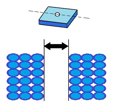
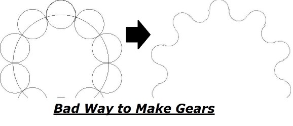
Why Involute is Important:
It’s really common to see gears improperly designed by the hobbyist community online because doing it the right way is hard. Tempting as it may be, poorly designed gears don’t mesh properly and suffer from excessive friction, stress, backlash, and jerky uneven rotational velocity.
The difference is subtle to the untrained eye, but doing it the right way will be more accurate and have better properties in the end.
Involute (spur) gear teeth are called such because the contour of gear teeth has a special curve inward. This is done in such a way that ensures the rotational speed and angle of contact of the gears stays constant throughout their rotation. A well designed set of gears should transfer motion almost exclusively through a rolling action, with very little sliding involved.
Modelling involute gear teeth from scratch is tedious as hell so before taking the time to do it, first check if you can get by with one of the gear design templates I link to at the end of this article.
.
Tooth Design Tips:
Think about this: If you wanted a 2:1 gear ratio for that linear actuator pictured earlier, how many teeth would you put on a pair of gears to achieve it? Are you better off with 30 & 60 teeth, 15 & 30, or 8 & 16?
Each of those ratios would have the same mechanical advantage but each would be a very different set of gears if printed.
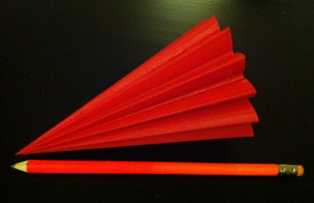
More teeth per gear increases the contact ratio (average number of teeth in contact at any time) and provides smoother rotary motion. But adding more teeth requires that each tooth get smaller to fit on the same diameter of gear. Tiny teeth are weaker and more difficult to print accurately.
3D printing a tiny gear is like trying to use a thick sharpie to color inside the lines of an itty bitty coloring book. (This is 100% a function of nozzle diameter and X-Y resolution of the printer. The Z-resolution has nothing to do with minimum feature size.)
If you want to test your printer’s ability to print tiny teeth, try this free 3d printable bevel gear model test. My printer makes it all the way to the top but the teeth start looking untrustworthy around 1/2″ diameter.
Alternatively, reducing the number of teeth on a gear gives you more space to have large strong teeth.
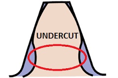
The trick is to keep the gear teeth as large as you can get away with, without crossing the low-tooth-count threshold or introducing undercut.
One more thing to consider before picking the tooth count: Prime numbers & factorization.
The 15 and 30 tooth gear pair are both divisible by 15 so the same teeth will meet up over and over again causing concentrated wear points.
A better solution is to make the pair have 15 & 31 teeth.
While this doesn’t produce exactly the same ratio, it will provide a consistent wear on the gear set. Grime and imperfections in the teeth will spread across the whole gear rather and distribute the wear.
Also, it’s a good rule of thumb to keep the tooth ratio between be between 0.2 and 5. If you need even more mechanical advantage it may be better to add an additional gear stack into the system, else you end up with a 1000 tooth monstrosity.
How few teeth is too few?
This is information that can be looked up in resources like the Machinery Handbook. 13 is the minimum recommended for gears with a 20 deg pressure angle, and 9 is the minimum recommended for gears with a 25 deg pressure angle.
Fewer teeth that that are not recommended because it would require undercut, which weakens the teeth and is tougher to 3D print without having meshing problems.
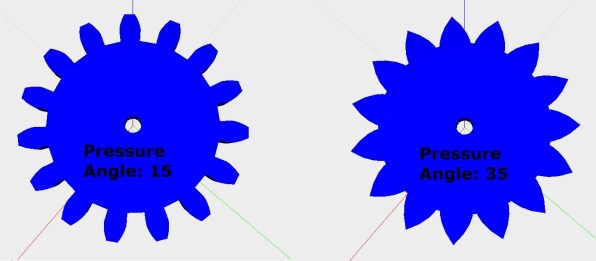
Pressure angle? What’s that best one?
This is the angle between the normal of the tooth face and the pitch diameter. Teeth with larger pressure angles (more triangular) are stronger but are also less efficient at transferring torque. They are also easier to print, but in use they create larger radial loads on the supporting shafts, are more noisy and prone to backlash and slippage.
For 3D printing a 25 deg angle is a good balance of chunkiness and efficient motion transfer on a palm sized gear.
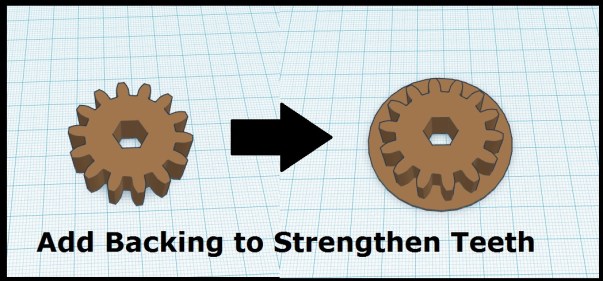
How Else Can I Make Teeth Stronger?
Simply making the gear thicker will obviously strengthen the teeth as well. Doubling the width of the gear essentially doubles its strength. A good general rule is for the thickness to be at least three to five times the circular pitch of the gear.
The strength of gear teeth can be approximated by considering each tooth as a small cantilever beam. When viewed this way you can see that adding a solid wall over a face to reduce the unsupported area greatly increases the strength of gear teeth. Depending on the application, this technique can also be used to help reduce finger pinch points.
.
Shaft Mounting Methods:
Press Fit on Knurled Shaft: The easiest method to do but is not seen very often. Watch out for plastic creep which will reduce the torque capacity over time. Cannot be disassembled.
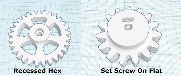
Set Screw on Shaft with Flat: A setscrew is driven through the gear to contact a flat spot machined on the shaft. The set screw is usually threaded into the plastic gear directly or through a nut that is trapped inside the gear via a square hole. Each method has its own risks.
Directly threading into the plastic runs the risk of stripping the delicate plastic threads. The nut trapping method solves this problem but if not done properly the hub breaks when you apply enough force to secure the shaft with the set screw. Make the hub Beefy!
Recessed Hex– a hexagonal well which traps a hexagonal nut or the head of a hex-head bolt. Make sure to print lots of solid layers around the hex so that a mounted bolt cant strip through the plastic. Ive successfukky used set screws to secure nuts in place to prevent spinout at high torques.
Key & Keyway– Not often seen in the hobby 3d printing world, but is the standard for metal sprockets.
Optimal Materials for Plastic Gears:
What is the best material? My short answer for the hobbyist 3D printing community from the perspective of finished gear quality:
Nylon > PLA > ABS > PETG
Nylon filament is an incredibly strong, durable, and versatile 3D printing material. It’s low friction coefficient, high inter-layer adhesion, and high melting temperature make it an excellent choice for 3D printed gears. The drawbacks of nylon are its propensity to absorb water and the difficulty of printing with it.
That leaves most folks with the choice between ABS & PLA. PLA has high rigidity and superior wear properties over ABS which make it a better choice when application temperatures allow.
PLA’s low heat distortion temperature makes ABS a better choice for applications involving temperatures above ~75C (ABS softens around 105C).
By the way, the biodegradability of PLA is an overhyped property. Yes, PLA is biodegradable. But not in a scale that is in any way noticeable for the end user. Do not equate biodegradability with water solubility. To biodegrade this plastic, you need a specialized composting facility with a controlled environment.
Edit: Added PETG after reviewing data on its material properties here and here I am putting it at the bottom of my tiny list. While it is a ductile material it is also softer, more flexible, and less scratch resistant than either ABS or PLA which makes it a worse choice for gears.
Special Tips by Gear Type:
*Helical & Herringbones (double helical): Usually seen on printer extruders, these are annoying to use, but have their merits. They are useful for their ability to increase contact ratio, self-center, and self-retain. (Self-retaining is the annoying property because it makes installation more work.) This type of gear also can’t be easily manufactured with conventional machining equipment like a gear hobbing machine. 3D printing is by far the easiest way to make them.
*Worm & Worm gear: These can be difficult to 3D model so its very tempting to use a ger template for these. My tip here is that the gear ratio between the worm gear and worm is the number of teeth on the gear divided by the number of flutes in the worm. (Count flutes by looking at the end of the worm and see how many spirals start. Most have 1 to 3 spirals.)
*Rack & Pinion: Converts rotary motion into linear motion & vice versa. Rather than rotations, the gear ratio determines the linear distance traveled by the rack with each rotation of the pinion. The tip here is that you can calculate the gear teeth per inch (tpi) of a rack all you do is multiple PI times the pitch diameter of the mating pinion gear. (Alternatively multiplying number of pinion teeth times circular pitch produces the same result.)


Non-circular gears like these nautilus gears have no practical use I’m aware of other than novelties.
.
Lubrication of FDM printed gears:
You can get away with operating plastic gears without lubrication in light-load low-speed low-frequency applications. Toys for instance. But if you have a higher stress environment, like a 3D printer extruder, you can increase the working life by lubricating the gears to reduce friction and wear.
For 3d printer extruder gears I recommend heavy grease. White lithium, PTFE, or silicone based are all great stuff for this. Apply the lube by wiping lightly with a clean paper towel or dust-free cloth applicator, and spread evenly by rotating gears multiple times.
Anything is better than no lube, but be sure to choose a lubricant that is chemically compatible with the plastic material. And never forget, WD-40 sucks.
.
Tools for Making Your Own Gears:
You can create great quality custom gears using only free software. I mean sure, paid programs exist for creating truly optimized gear meshes and tweaking very fine parameters to optimize performance.
But if you are using FDM 3d printed gears anyway, then good enough is good enough. Just be sure to design all your gears using the same tool to ensure that they mesh as intended. Gears are best designed in pairs.
*Option 1: Find existing gear models & modify or rescale them to suit your needs. Here is a list of databases to find models of off the shelf gears.
McMaster Carr: wide array of 3d models, go-to for hardware
GrabCAD: Huge database of user submitted models
3DContentCentral: Database of user submitted models
Misumi: 3d models of small mechanical parts
Stock Drive Products: 3d models of gears
.
*Option 2: Designing gears ‘from scratch’ using free online gear generating templates:
If you can’t get the right details you need by copying an existing model, the next best option is to use an involute gear generator template to make your own custom gear. Fortunately there are many cool tools out there to help.
- I created a collection of useful gear models that can be customized on Thingiverse: http://www.thingiverse.com/MechEngineerMike/collections/gears-customizable
- Matthias Wandel’s classic gear generator program: http://www.woodgears.ca/gear_cutting/template.html
- Online STL File Creator, simple & direct: http://joostn.github.io/OpenJsCad/
- Generate Spur Gear SVG Files: http://geargenerator.com/ (That file can then be converted to an importable DXF file type here: https://cloudconvert.com/svg-to-dxf)
- Another in browser super gear generator: https://evolventdesign.com/pages/spur-gear-generator?fbclid=IwAR046afSro_yAcQoKwzn8VM2AeeSm6WVTla3JNKCgZc9CjiaFxa_-ep9j0g
STL File Editors:
The output of most gear template generators is an STL file, which can be annoying if you need to make features that aren’t in the generator. STL files are like the PDF file of the 3d world, they are notoriously difficult to edit but it can be done!
- TinkerCAD: I love this silly browser based CAD because it is quick and easy, and one of the rare 3d modellers out there capable of modifying STL files. www.Tinkercad.com
- MeshMixer: Good program for stretching out organic shapes. http://meshmixer.com/
.
That’s all the 3d printing gear design notes I’ve got for now. Do you have any more resources or gear templates to add to the list? Let me know in the comments!
UPDATE: Enhanced version of this article now on Instructables.com here.

Nice bit of work. Thanks for sharing.
I’ve been using PET-G recently, and it is far better then ABS or PLA. I haven’t tried nylon though, so I’ll give that a comparison test.
LikeLiked by 1 person
Thanks, Ill look into that one!
LikeLike
Dear Sir:
GearGenerator.com now charges to download a STL or CVS file. If you are just playing around, you may want to skip this web site.
LikeLike
Thanks for the tip! And if SVG files are still free then you can ‘stick it to the man’ by converting that into an STL youself. Tutorial here: https://engineerdog.com/2018/01/18/how-to-convert-an-image-into-a-3d-printable-file/
LikeLike
Just over the holidays I was wondering about designing and printing gears on my Taz printer. Most excellent article!!! Thanks Michael!
LikeLiked by 1 person
Thanks Enrique, I’m glad you enjoyed it!
LikeLike
Give POM/Acetal/Delrin a shot. We used that in injection molding to make most gears wear items. Not sure how it 3D prints.
LikeLiked by 1 person
Thanks for your comment! Yes acetal is our go to choice for molded gears at work, but unfortunately that material is not available on FDM type 3d printers to my knowledge. BTW love the email address, resume contact info worthy stuff right there. 😉
LikeLike
I think the problem with acetal is that it’s a “crystalline” plastic, like Nylon. They tend to have a sharp transition between solid and liquid. FDM/FFF likes a nice gooey phase in between solid and liquid. The Nylon for FDM has been formulated to make it gooey over a wider temp range than pure Nylon, so there is hope that something similar will happen for POM/acetal/Delrin.
LikeLiked by 1 person
UPDATE: Decided to give away the gear switch model & expand on the guide here: http://www.instructables.com/id/A-Practical-Guide-to-FDM-3D-Printing-Gears/
LikeLike
Great article! I often print gears for use in MRI research equipment, and have found this terrific resource for designing gears online and importing directly into your 3D CAD program (I use SolidWorks):
http://www.rushgears.com/tech-tools/part-search/build-custom-gears
LikeLike
Great article here! We’ll feature it on our blog, if that’s alright?
LikeLike
Thanks a lot for all the info! I’m trying to fill my own experience sheet with different material properties, but this is a whole load of information I was planning to figure out in the future. I’m also designing my first design that contains gears, and I’m tying to make my own gears, but it seems really complicated stuff.
Again thanks for all the info, and the materials and lubrication really is in sync with what i’m experiencing.
There is one other filament I’m interested in for gears. Its nGen (I only know it from ColorFabb). it seems its almost as stiff as PLA, but has higher melting temperatures and if I’m right its UV en weather resistant just like PETG. The only downside I think it has is that it might have higher friction and wear compare to PLA, but unsure about that.
LikeLike
Glad this helps you! Ill add to take note of who this article is coming from, i like to optimize things to the nth degree. But if you are making a toy for fun then whatever works works, dont let me make it more complicated than it needs to be 🙂
I have not heard of nGen before. Trying to focus on a new project at the moment so not planning to revisit this work at this time.
LikeLike
What is smallest gear that you would recommend printing, in terms of diameter ?. The gear should be functional as well.
Thanks
LikeLiked by 1 person
That is a good question. It depends on how well they need to function and how many times you are willing to iterate to get it perfect. My little test showed teeth starting to look not so trustworthy at 1/2 inch outer diameter and below. But I know with a smaller printing nozzle diameter (i used 0.4mm) I could print smaller successfully.
LikeLike
Thanks !! Will give it a try and let you know how it goes.
LikeLike
I’ve used the FreeCad involute gear generator down to a modulus of 0.625 mm with 11 teeth. That’s a pitch diameter of 6.9 mm, or 0.27″. They work beautifully. Used my new Prusa mk3S with PLA at 0.15mm resolution and a gear thickness of 1.95 mm (13 layers at .15 mm). Could probably push it further, even with the standard 0.4 mm nozzle.
LikeLike
Nice article! I’d recommend to use FreeCAD for serious modeling, especially if you need to design also other stuff around the gears. Usually you want to create more or less complex assemblies. It has FCgear macro for creating common gears in 3D. I have no direct expericence with 3D printing, but here is a manual https://www.freecadweb.org/wiki/Manual:Preparing_models_for_3D_printing.
LikeLiked by 1 person
Awesome Ill have to check it out thanks for sharing!
LikeLike
FreeCad is very finicky. Try OnShape. It is the latest in 3D CAD. It has a spur gear generator.
A 3 Motor Gearbox with the smallest gear being ~0.33″ with 6 teeth. Pressure angle 20 degrees. Printed on a MonoPrice Maker Select V2 with PLA.
Why 3 motors. This gear box drives a set of spider legs of significant size and needs significant power and I chose to stick with smaller motors. Plus it looks cool.
LikeLike
I need a plastic piece off the gas hand control on a 1970 Indian mini mini motorcycle… we have the piece it’s just broke … Where can I pay someone to make this
LikeLike
This group on facebook (‘3d printing for profit’) has tons of people with the tools and skill set you are looking for: https://www.facebook.com/groups/151614475396174/
LikeLike
Nice article, thanks! I’m trying to refurbish an older printer that is missing the small herringbone motor gear shown in your article labeled “The ubiquitous 3D printer extruder gear drive.” My printer (airwolf 3d) can’t be used to make the part I need, so kind of a catch 22. Any ideas on where to find one? I’ve already talked to Airwolf and done extensive searches, but to no avail. Thanks for any leads….Craig
LikeLike
If you search herringbone extruder gear on thingiverse, there are many. But it sounds like the broken part is FROM your airwolf 3d printer? If thats the case that company should make you one, for free if it is in warranty. (Perhaps free even if it is not, as that is not something you should have to replace.) If they wont make it for you at any price then you should get the stl file from them & have a friend make it for you. If airwolf is refusing to support their own product then attack them on social media i guess. 🙂
LikeLike
Thanks for getting back to me. The Airwolf unit is one of their older models and was given to me by a friend with the part missing, so there’s no warrantee issue. I was just trying to see if I could get it working, and was running out of ideas, so I posted on your site because I saw the part in a picture. I’ll keep on trying….. Thanks again.
LikeLike