Many years ago a young me looked at the differences between my grandparents two cars, Buick LeSabre’s of different model years.
“Grandpa, it’s weird that cars are all so different. They put so much work into making all the unique pieces that go into them. Why bother to make them different when they all do the same thing? Wouldn’t it make more sense to design the best car with the best parts and reuse them over & over again?”
He smiled and told me ‘They remake them differently as they learn how to do it better. They do reuse parts sometimes, but cars are different because they’re intended for different purposes. They’re optimized for different things.’
Here I sit 25 years later thinking about how his words apply equally well to my current career focus, industrial automation.
Controls engineering isn’t known for being a sexy occupation, but reshoring American manufacturing is definitely one of this season’s hot topics. Humanoid robots may dominate the social media feeds, but I have a hard time imaging those materially affecting our lives any time soon. In my opinion there is likely far more potential to increase productivity & bring the good jobs back home to be found by focusing on a more foundational tier: Applying modern software approaches to improving traditional manufacturing automation.
This post details a mental model that will be useful for other engineers entering this field.
…
Designing better machine controls & device networks is an interesting problem (to me), but the rabbit hole is deep and it requires discerning various tech of similar names & capabilities. Literally everyone I talk to with my job title has vastly different end-uses, problems, experiences, strategies, & toolboxes!
There is a dizzying array of industrial automation tools/terms/brands out there with overlapping capabilities that blend together into a gray mush of confusing vernacular: IPC, PLC, DAQ, SCADA, PAC, DCS… HMI, GUI, Touchscreen, Web Interface… EtherCat, EtherNet, ProfiNet, ProfiBus, modBus… OPC-UA, MQTT, HTTP/REST… LD, ST, SFC, IL, FBD? Similar, but different!
Automation software/controls engineers have to stich together super specific solutions using various pseudo-compatible hardware, networking software, IIOT devices, & proprietary solutions. Hardware, electrical, software… it’s full stack engineering. Difficult but satisfying & important because this tech has tremendous value-added effects!
…So I’m often coming across something new and asking myself, how the heck could use this thing with my system?

To add to the complexity this industry is currently undergoing a period of rapid change as we figure out how to integrate web technologies into new systems deployed alongside reliable old ones we refuse to let die! (Nothing about hardware or factory upgrades is truly rapid)
The core technology of Programmable Logic Controllers (PLCs) has been around since the 70’s when companies were starting to replace electrical relay logic with devices that used embedded software instead. We’ve come a long way in 50+ years as new capabilities continue to come out and prove themselves robust enough for industrial use.
But the use of industrial controls in manufacturing is a laggard in the tech world. Complex machines heavily integrated into production lines require significant capital investment & man hours to setup. Once operational, human nature takes over and the prevailing attitude becomes ‘If it works, don’t touch it!‘
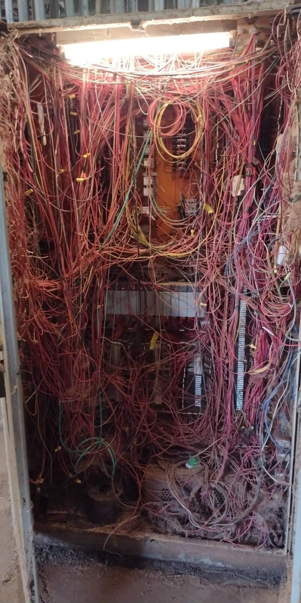
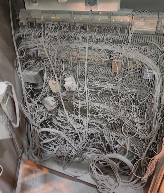
When a machine is expected to outlive the career of its creator and run for 15 years with minimal downtime in an extreme environment, it’s easy to see how we end up with this kind of thing: (image credit reddit.com/r/PanelGore/ the existence of which suggests how common this is!)
My personal interest here is simply trying to make sense of it all so I can do what I do even better! I’m less concerned with precise definitions of various acronyms than I am with understanding the logic behind the design decisions for when to use what.
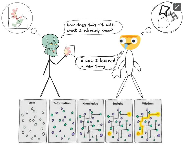
To that end, the best way to proceed making sense of things is to create a mental model; a mental map of the automation hardware territory! Arranging facts into a coherent story helps you develop an intuition, so when you encounter something new you can better determine how the new puzzle piece fits into what you already know.
Things are mostly defined by what they aren’t, so lets start with the most basic system and let the limitations define some boundaries.
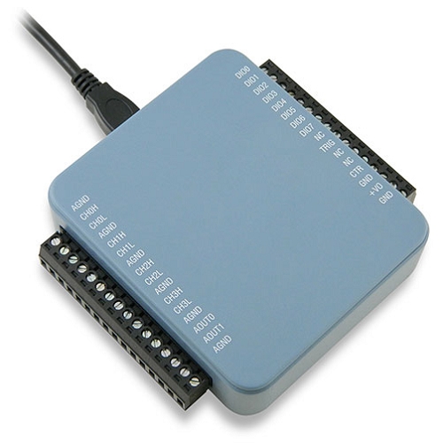
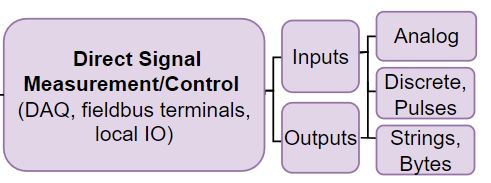
The ubiquitous USB Data Acquisition (DAQ) device is a perfect encapsulation of a simple signal measurement system. Computers interact directly with the physical world through electrical signals of a pre-defined scope. There are many standard methods used but all of them can be grouped together into 3 abstract types.
Imagine we rig up the DAQ to interact with a set of digital calipers. It can read/control the power state, a Discrete signal which is either ON or OFF. The caliper’s distance measurement is an Analog signal between 0-100% of its full scale range. And the caliper’s OLED display might be some byte array that decodes to ‘INCHES’.
This is ALL it can do, a DAQ a brainless incomplete system on its own.
You need a computer to interpret the information and give us a way to interact with it, a human-machine interface. With simple DAQ software running we make a system that could turn on a heater relay (Discrete Out) as it measures the air temperature (Analog IN), while you monitor & control the system from your laptop.
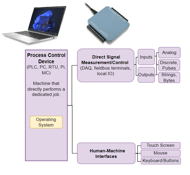
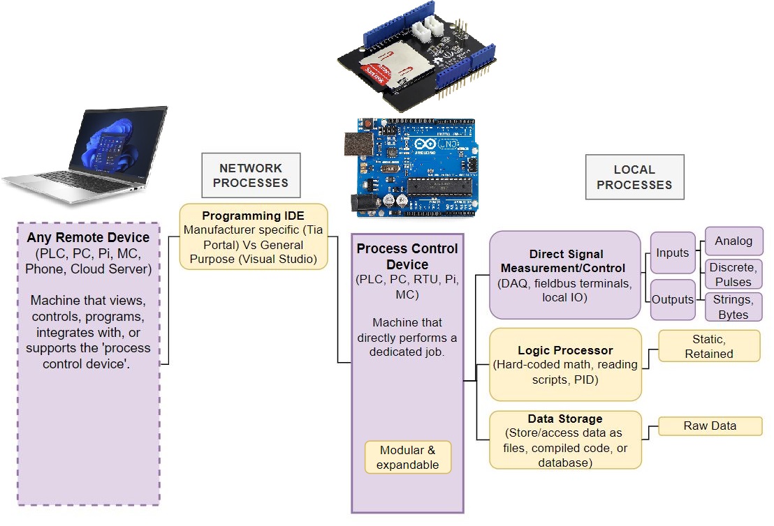
That’s a good start but likely you don’t want to dedicate an entire PC to a simple job full time. So you could expand the complexity a bit and delegate the process control tasks to an arduino.
The PC’s new role is limited to providing the initial programming. Arduino can use its own hard coded (static) logic to activate the heater relay when the room is too cold. Unlike the DAQ the arduino is modular so you can expand it with an SD card shield to record the temperature over time as a csv of raw time series data.
The customizability of DIY embedded systems is powerful so this setup can get you pretty far! Maybe you get ambitious and use it to say run a motor controller for a simple conveyor belt in your factory.
Assuming 10 bit resolution is adequate, it might work initially, but eventually the limitations will become obvious.
For starters troubleshooting a finnicky arduino controlled system can be painful. The embedded code is completely invisible so runtime info can’t be viewed live without a ton of serial.print commands to help spot problems.
Plus the arduino is going to have a tough time surviving in a harsh environment long term. All it takes is someone getting the bright idea to manually back drive the conveyor motor spiking its voltage to releasing the arduinos magic smoke. If you’re not available, someone else is going to have dig up your program, force your fault signals false (ha!), and redo the hobby grade wire headers.
Even the csv data itself can limit you as eventually you start needing answers a csv can’t tell you directly. You have to make an elaborate excel document to parse the raw data to extract the implied insights you really care about: distilled data such as the average time between specific events.
You’re really in trouble when its time to grow & suddenly you need to control multiple conveyor belts 200ft apart in tandem. And add a local display with controls and user logins. And displaying the same information in your control room. And. and. and. andddd….this tool is inadequate for industrial use for many reasons.
A PLC can come with a significantly higher price tag, but its the cost of buying into the manufacturer’s proven infrastructure. The bulletproof physical design, long term parts availability, the superior programming interface & networking capability. In practice the initial cost matters much less than the reliability & capability they offer.
Lets take it up a notch & use a CLICK brand PLC from Automation Direct as your process control device. It can handle voltage spikes in a rough environment, and use various standard industrial protocols to talk to whatever hardware you want. It has a ‘real time’ processor instead of an event driven one so it can synchronize motion controls with high precision. It’s modularity is readymade to add capabilities over time without undue headache.
To add local controls you could buy an ‘HMI’ for it (Confusingly the acronym means human machine interface but I use the full phrase more generically). An ‘HMI’ specifically looks like a computer monitor but its actually an expensive embedded system on its own that has to be programmed to communicate with tagged variables hosted by the PLC program. A pain to add for the overhead but overall an excellent tool for lasting the test of time.
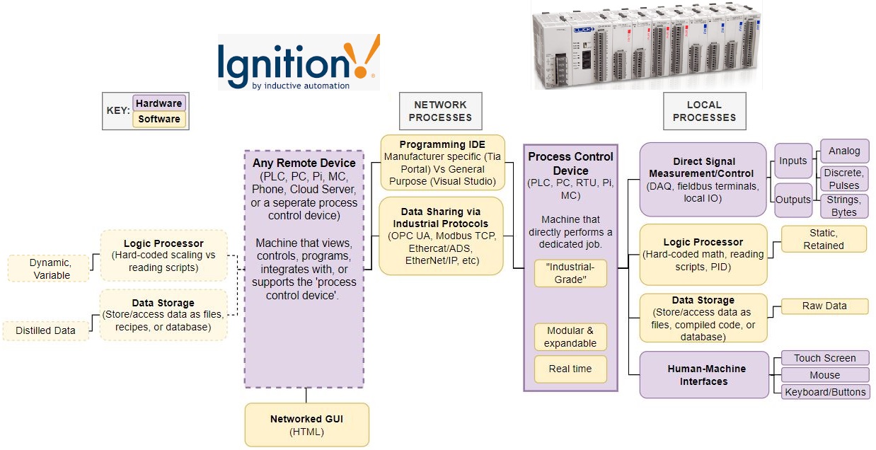
Better yet, buy a software license for a centralized SCADA (Supervisory Control and Data Acquisition) system like WinCC or Ignition, and your factory is set to grow. On the back end, Ignition exists to provide an internet hosted GUI, a logic processor for extracting distilled data, and a proper SQL database for storing it. Best of all, Ignition can be used as your factory hub, a central point of interaction for all the PLCs deployed in your factory!
This is a capable & scalable setup, what more could you want?
Welllll… as the old man said, there is no one size fits all best solution.
A central hub means your entire system is vulnerable should an engineer fat finger the wrong button (or Ignition just eats up all your web client’s RAM!) But the big limitation I see is that the PLC delegates all of its higher level processes to the SCADA. A basic PLC is still limited by static logic only, that is, you have to compile & push an update through its IDE to change its runtime code. An undesirable characteristic in a dynamic high mix environment. Sometimes it’s just better for the process control device to be super smart on its own.
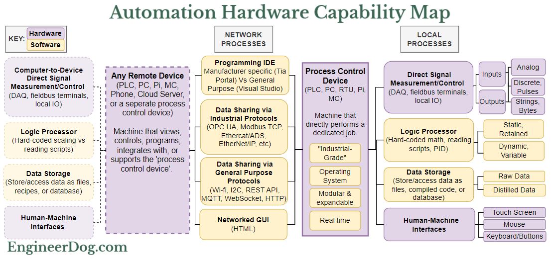
The Full Capability Map.
The next generation of hardware after PLCs recognized the value of adding a standard operating system (Windows/Linux) onto the PLC itself, running in parallel. Making it into an Industrial PC (IPC). This unlocks the rest of the capability map!
With the full map you can mentally hash out the relationships of where & how operations are occurring. Not perfect perhaps but a useful way to think!
IPCs are my first choice due to the need for rapidly made stand alone deployments & overall variable nature of problems I need them to solve.
My preferred PLC environment is Codesys; a software company that tries to be hardware agnostic so you can use one familiar interface on lots of different devices. On its own it can make a process control device do anything you want on the map! However, Codesys can do anything but not everything well. Fortunately, the IPC’s OS gives you a file system, an HDMI port, and allows you to run other programs in parallel. Running Python in the background and OPCUA to share information between the two processes unlocks a ton of capability with each tool doing jobs it is best suited for.
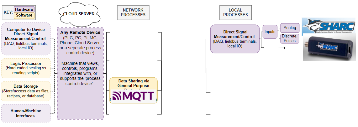
For smaller project we often use a Raspberry Pi (“soft PLC”), connected to Beckhoff hardware for IO and networked to our server for data saving & configuration distribution. In practice the deployment map looks like this:

This image, I think, really communicates the value of the map. There is no end to the list of customer wants so we have to get creative to accommodate! Checking everything off the list is complicated and requires forethought on your approach. (Doing so in a live factory with business needs demanding rapid results and little downtime is even harder!) But when done well these tools are incredibly powerful. An order of magnitude more capable than what was possible even 10 years ago. (More on these another time!)
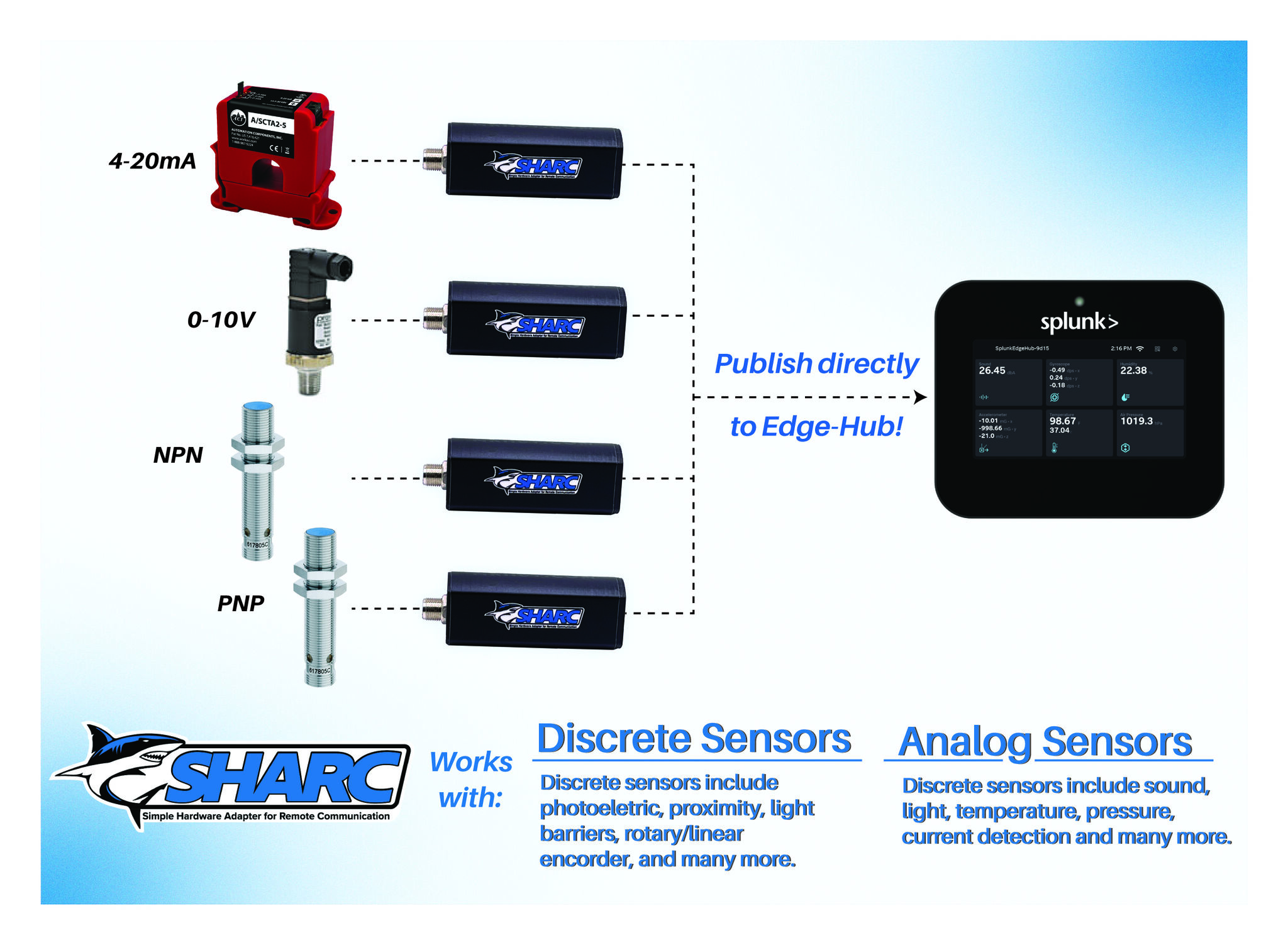
A final example, back to the very first picture in this post asking ‘what the hell is this?’ The ‘SHARC IoT Sensor Adapter’ is an oddball. An incomplete system on its own, not even a full process control device, just a networked DAQ of Inputs only. With data shared over MQTT you have to access with your own separate tools. Probably useful for a spread out factory where all you need to do is monitor that things are running OK.
Beyond that I know there are so many tools I still haven’t gotten my hands on yet. To be fair I don’t think anyone knows everything in this domain, there’s too much and it’s growing! The possible applications get ever more niche, and there’s always a better approach/tool/brand/library. You just have to pick a favorite toolset then dig in and make the dang thing work!
If this sort of thing interests you I highly recommend taking a look at SASE, the Society of Automation Software Engineers. A growing community of people wrestling with all of the above to deploy the cutting edge tools we’re going to need for a successful American manufacturing revitalization story. Good folks, all of ’em nerds!
That’s all for now, hope that helps!

(Diagram tool I used throughout is https://app.diagrams.net)
-Think my map missed anything important? LMK! I’ve got plenty of blind spots no doubt. This is post intentionally introductory and I left out discussion of qualities within a categories (cost & ease of use between brands, bit resolution, protocol popularity, recipes vs csv files vs json etc) to focus on the big categorical differences of what things do and how they interact.
