The Problem: 3D printing is new enough that there are still many questions that do not yet have definitive answers.
What is the best adhesive to use? What is the strongest lattice/perimeter combination? At what point does increasing infill have a significantly diminished return for strength? How can I get the best quality print in the least amount of time, and will printing faster reduce my layer adhesion strength? What is the effect of surface finishing treatments on material strength & dimensional tolerances? And on and on.
Very few people can speak with authority on these subjects. I believe that most of the information I’ve read online through 3d printing forums and various articles is primarily based on anecdotal experience, hearsay, and best guesses rather than hard data.
If you want to do some actual engineering design of 3D printed parts the best you can do right now is estimate some mechanical characteristics using rough hand calculations or stress analysis software. Both methods are limited in their ability to accurately predict reality because they cannot consider artifacts of manufacturing or complicated internal specimen geometry. These are significant drawbacks especially considering that the most common type of consumer grade printers use fused deposition modeling (FDM) to print, which results in a directional grain similar to wood.
The only reliable way to shut off the tap of unwarranted opinions is to do some actual testing. Of course professional grade testing has been performed on 3d printed objects before. Basic properties of raw ABS and PLA materials are well covered ground. There is no debate about the density, modulus of elasticity, or melting point of those materials.
What I’m curious about are clearly some of the more esoteric material properties. For example, the best study I’ve yet seen on the subject of lattice structure happened to come out last week. It’d say it’s a good start and I’m anxious to see how my results will compare to theirs.
..
The Plan:
While I have seen a few other DIY attempts at testing 3D prints, the choice of equipment and procedures used always leaves something to be desired. The most common issues I’ve seen are:
*Using force sensors with high variability and no calibration, such as a fish scale. ~*shudder*~
*Tensile tests being performed with tools like high speed cable winches, which do a poor job of controlling for strain rate. This is a particularly significant concern for plastic specimens which may even see different failure modes and ultimate loads because of strain rate. (To understand how this could happen imagine how ‘sillyputty’ reacts differently when it is pulled quickly vs slowly.)
*Counting tensile specimens that fail outside of the gage section as valid tests. Come on people. It’s OK to exclude data from your set if it’s obvious that the test was affected by outside variables, such as poorly designed test fixtures/specimens.
*Only testing specimens via tensile loading, rather than using other standard test methods.
.
That last note is particularly important because I intend to run many tests using a 4 point bend setup. This test method is exactly what it sounds like:
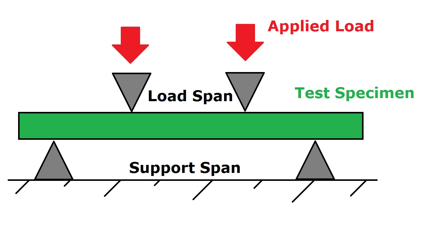
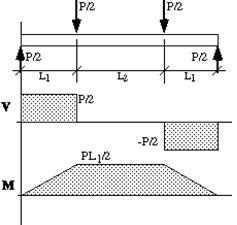
A V-M Diagram shows how the force (V) and bending moment (M) change over the length of the specimen.
.
The four point bend is actually a great method for testing non-homogenous materials. I’m using it here for these specific reasons:
- It is a ‘realistic’ loading method. If I were to ask you to break a random small object such as an iPhone 6 your natural inclination is to apply a four point bend.
- It requires a simple specimen and test fixture design that really can’t go wrong.
- This type of test is sensitive to surface condition because the largest stress occurs at the extreme fibers of the specimen, the outer surface. For this reason I expect that certain surface treatments will have a significant effect on the measured material strength.
- The 4 point bend loading causes complex stress distributions over a large volume of the specimen, so any flaws or defects will be easily exposed.
..
Aside from the four point bend tests I will run some other basic types as well. What follows is a general plan of tests on my to-do list. Feel free to share any suggestions of other tests you would like to see performed.

In all cases the data recorded will be as follows: load, displacement, load rate, specimen mass, measured specimen dimensions, actual print time, ambient condition, and filament brand.
..
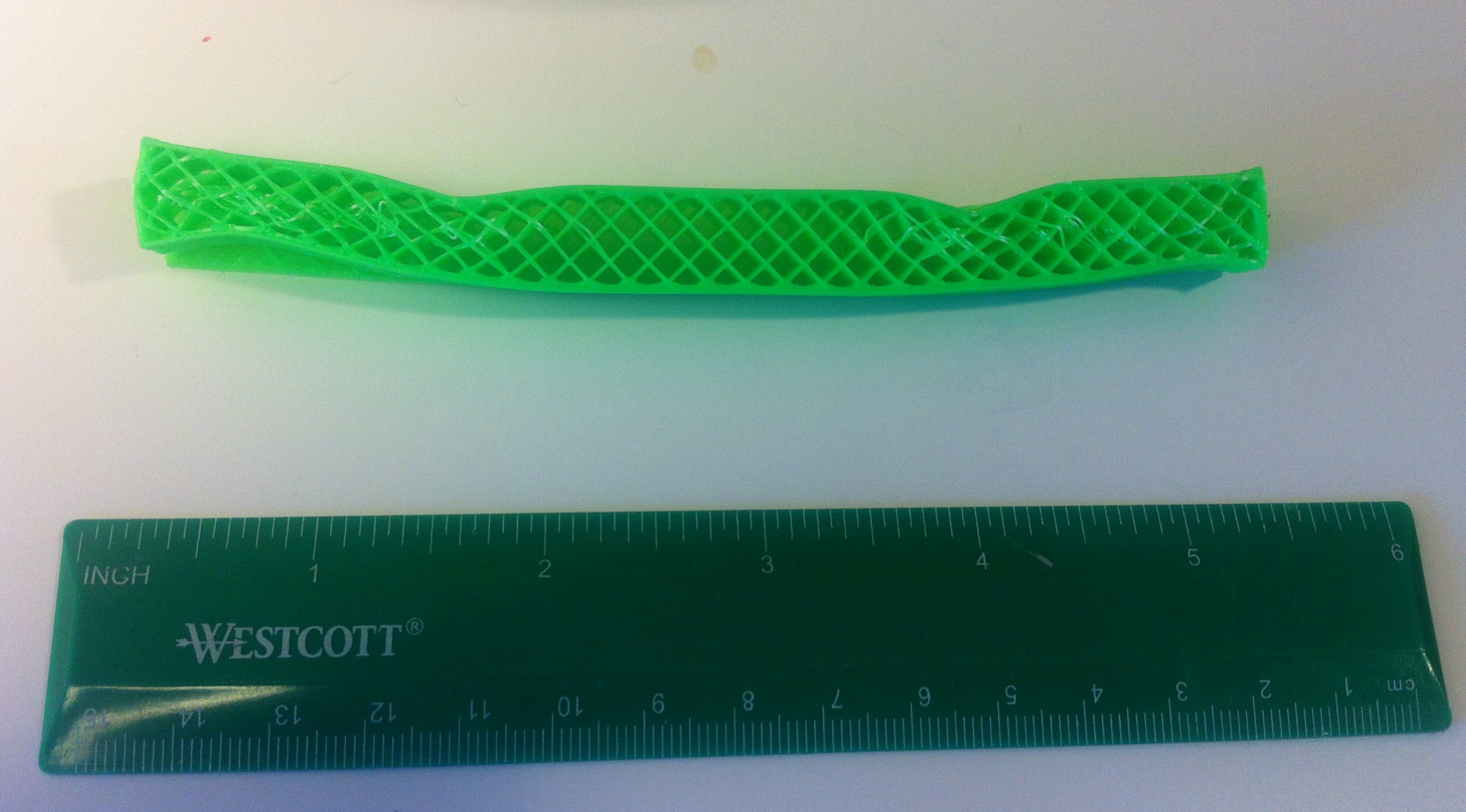
The Prototype: An experiment within an experiment
The more I play with this little project, the larger its scope has grown. What once started as a distraction, has become the primary focus of my free time efforts. Since making the prototype shown below, I’ve ended up going with completely new design based on a homemade electro-mechanical linear actuator (a design I’ll be sharing next time). What is shown here is the initial prototype.

Not Shown: The massive 3 HP air compressor running in my little apartment.
The frame itself was intended to mimic a RepRap, consisting entirely of 3D printed parts and steel hardware. Using printed parts here makes it possible to create this machine using nothing but a 3D printer and a wrench. It also ensures that the frame has perfect dimensions and alignment, a huge benefit to the overall quality of the machine. Oh, did I mention I like the pretty colors too?
The main innovation used in the frame is a beam design technique called sandwiching. The idea is to glue two thin steel sheets onto either side of a lightweight printed core to create a structure that is significantly lighter than a solid steel beam while still retaining the majority of that beam’s strength and stiffness. This method is often used in things like aircraft wings, only with composite skins and balsawood cores.
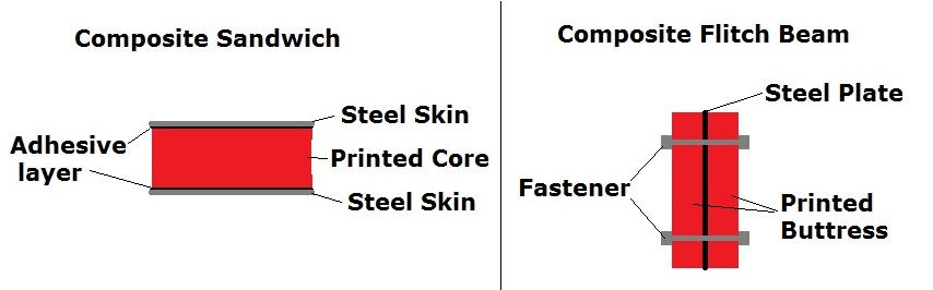
Sandwich beams are quite similar to another beam design technique, the flitch beam, which uses the weaker material to buttress the stronger one to prevent buckling.
In practice gluing the steel to the plastic has proven tricky. The adhesive layer’s resistance to shear force is critical to the sandwich beam strength, so the choice of glue used will make or break this design. All I can say is that an acetone/abs slurry does not work.
Believe it or not the frame still held up to a 200 lb test load without issue, though that may have been primarily due to the 1/2″ threaded steel rods running through the beams.
Cutting out the steel sheet was pretty labor intensive, so I probably should have used something else as the skin. Sandwiching was a fun experiment but in the end I think using a wood two by four is a better option for now.
Moving on to a practice test:


Yes, all test results will be reported in US customary units.
What did I learn from this little experiment? Well for starters my displacement resolution was terrible. The 2.36” sliding potentiometer and 10-bit Arduino combo should be capable of sensing distance increments as small as 0.0023” (that is, 2.36” divided by 1024 sense-able voltage increments). But I accidentally rounded off my data at 2 decimal places, so that run has displacement in increments of .01”. In any case the next iteration will use a different method altogether and have a disgustingly high degree of distance measurement resolution.
The choice of an air cylinder was short sighted but in my defense that design decision was heavily influenced by my ability to get one second hand for $10. Since I was unable to find a cheap and easy to install needle valve to precisely control the air flow rate I had very limited control over the actuator. The control problem, the otherwise normally high cost of air cylinders, and the need to use a noisy air compressor are all good reasons not to use an air cylinder going forward.
The one thing that worked perfectly right off the bat was the load cell and data acquisition combo. I always try to make personal projects as affordable and replicable as possible so I used an Arduino Uno, an $8 INA122 chip, and an off the shelf 200 lb load cell. I feel a little limited with the resulting .195 lb resolution, but at least the signal is steady and repeatable. I was able to verify it with weights at the gym and I intend to get a certified calibration done on the whole system.

[…] tests were run in a static 4 point bend configuration using […]
LikeLike
Excellent and very useful to me.
LikeLike