When I worked at a mechanical testing laboratory one of the most common frustrations I encountered was the need to use appropriately sized clevises for tensile testing. Running a tensile test is simple…in theory.
All you have to do is grab a test specimen on both sides and pull it until it breaks. Then you use the data you hopefully remembered to record to determine the mechanical properties of the specimen.
The frustrating part is that you have to use a correctly sized clevis for the job or risk public humiliation when your clevis breaks or otherwise affects your test. Now just take a moment and imagine how many possible dimensional variations there are of this: 
You might as well ask: “how many molecules are in my shoe?”
For this reason about once a week I found myself cursing my existence while sifting through endless piles of sharp-ass steel chunks in search of a clevis that may or may not even be there. Then I’d give up and spend 2 hours making one from scratch only to realize the moment after I finish it that the one I originally needed was in that other pile I didn’t check. Ugh. And so the quest began: I needed to design the ultimate adjustable testing clevis! How hard could it be anyway? Well after some serious thought it turned out there are definitely no obvious solutions to this one. This was my clunky first attempt anyway: 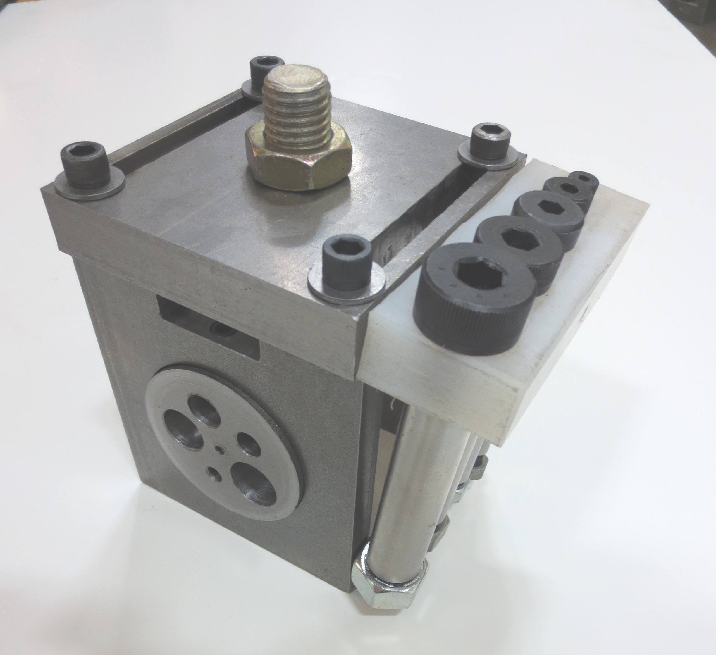 This version could fit five different pin sizes and the two faces could slide toward each other to straddle any width of specimen. Unfortunately, its strength was limited to the tensile strength of four 5/16” bolts (roughly 27,261 lbs thank you). Also this device was difficult to keep centered on the test machine, it couldn’t be used on really wide parts, and it was laborious to make.
Eventually I came up with the ultimate adjustable clevis design! I have a 3D model shown below next to some 12 inch rulers for scale. The black rings are shaft collars which are a standardized size and make excellent spacers for ensuring that the load is always centered. All the parts have set screws which lock onto the milled flat and prevent unwanted fixture motion. The big hole on the bottom was fit for hardened sleeve bushings to step down to the correct pin hole size.
The result: You can grab any pin size and any specimen width in a simple package!  But wait there’s more! This design could also be adapted for tensile testing ropes. This one is kind of hard to explain if you haven’t seen it done before but basically with the addition of the parts below this clevis can grip ropes or straps by wrapping the rope in and around the shaft, which then locks into place using the 4 hole pattern on the side. I think this thing would have solved a lot of problems for me; maybe I’ll get around to building it if I ever need to do some pulling.
  One problem will always remain for any clevis design, that they have multiple possible failure modes. The pin can bend or the clevis can tear out in two different ways, but you won’t know which way it will go until you do three separate calculations. If you’ve read my articles up to this point then you know by now that I’m not willing to sit down and redo the math every single time I use a new design. Unfortunately, the design work does have to be done because clevis failure can lead to very bad things.


Left: This clevis is used to pull trailers. Right: The reason I don’t like to drive behind trailers.
To save myself the trouble I created a calculator for determining the maximum loads and failure modes of the three most common clevis designs. While it might seem to be an oddly niche worksheet, you’d be surprised how often I’ve had to calculate the shear tear out strength of holes in beams. (For single shear just divide the rated force of a square clevis by two!) Here are some unavoidably blurry screenshots of the clevis calculator. 
