One inescapable truth engineers must face is that every manufacturing process comes with its own flavor of variations that need to be considered.
That is, no matter how you physically build a part there will be some degree of real world deviation from the perfect model designed in CAD. Anyone experienced with 3D printing understands that it is no exception to this rule.
In the case of FDM 3D printing, there are many variables that come into play on a person-to-person basis like filament material chemistry, printing hardware & setup quirks, temperature, humidity, and slicing software/settings.
The result is that 3D printed parts don’t always assemble together the way the designer intends. Especially if someone other than the designer is printing and assembling it!
In this post, I want to share some professional tips for creating robust designs that can absorb natural variations & facilitate mechanical assembly. These universal techniques can help you design parts that work on any 3d printer setup!
To provide an example of these tips put to use, I will use a brand new model I’ve been working on this spring. A 3D printed servo linear actuator that I’m entering in the 2018 Hackday Prize robotics module subcategory. Check out the project details here & watch the video below for a demo.
Properly Locating Parts for Assembly:
If proper functioning of your assembly relies on precise part orientation or if you care about ease of assembly, then design your parts with separate features for locating & clamping functions.
That is, don’t rely solely on your fastened connections to orient your parts during assembly! Instead add specific precisely controlled features for the express purpose of holding the parts in place while you attach them. Doing so has multiple benefits:
1. Accuracy: For a screw to physically fit through a hole it must have some amount of clearance. Leaving wiggle room is necessary for assembly, so relying only on screws to locate parts allows for a degree of uncertainty as to the final orientation of the mated parts
2. Ease of assembly: Adding specific features to square up your parts and hold them in place prior to screwing them down makes them easier to handle during assembly. No third hand required.
3. Error Prevention: Well designed locating features can prevent the assembler from assembling incorrectly. This is known as poka-yoke, a Japanese term for mistake proofing that encompasses different strategies all with that intent.
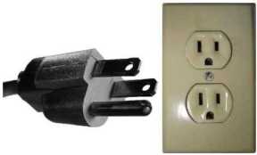
One application of this rule is to design assemblies with parts that are all very different or identical, but never design parts that are ‘nearly the same’ but not functionally interchangeable.
This rule extends to part features as well. The more axes about which a part is symmetric, the fewer possible incorrect assembly permutations there are. Having ‘nearly’ symmetric parts creates opportunities to reverse orient them and as the designer you can safely assume that if it can be assembled wrong, it will be.

A final note on poka-yoke; Reducing the total number of unique parts in an assembly simplifies your overall design, reduces cost, and reduces opportunities for assembly errors. My 3d printed linear actuator keeps it simple by using ONE type of fastener everywhere. ‘Plastite’ screws are great for plastics, no nuts or threaded inserts required! Huge benefits all around.
*OK great, locating features help in multiple ways, but how do you decide how many to add?
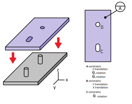
Well designed locating features will fully constrain parts together, but not over constrain them as in the example below. The intent is to account for 6 degrees of freedom, leaving each piece of the assembly in a fully deterministic position.
(The linear actuator assembly actually has one degree of freedom, the intended moving axis. Rule of thumb for robot arms, # motors = # degrees of freedom)
But wait there’s more…complications that is. Remember those unavoidable manufacturing variations? They affect the designated locating features too!
In the case of FDM 3d printing, fabricating a part in an unintended layer thickness or print orientation will completely disrupt the intended dimensions of controlled features.
That is why a model (stl file) by itself is an incomplete picture. So you should always include the specs too! What is obvious to you may not be to someone else. If it matters then explicitly specify maximum layer thickness, print orientation, & acceptable materials whenever you share a model.
*However, sometimes specifying fabrication details is still not enough to account for possible variations. In this case controlled compliance is a good strategy.
What I mean is you can mitigate the effects of 3d printing variance by designing designated elastic elements.


That is, intentionally design one piece for springiness or adjustability relative to its mating partner to get a desired fit or orientation. Designing this way solves multiple problems.
1: It saves you having to quantify exactly what you want the end fit to be. (Ultimately just saving you having to look up information in a table or do math but still.)
2: It saves you having to quantify precisely how the printed part will vary from the perfect model. Common 3D printing challenges & work-arounds include: printed circle’s are polygons (do math, or export higher polygon count), sharp exterior corners bulge out (fillet everything), the first layer thickness is uncontrolled (chamfer all bottom edges). Understanding likely natural deviations of printed parts vs CAD models takes experience, but lacking that research helps too. Best to go into battle with a good manual at hand.
3. Controlled compliance makes clear which part is to accommodate interference and which part is to remain unchanged. (Adjust your shoes not your feet!)
To wrap this up, I’d say in an ideal world assembling your design would be like an adult putting together one of those wooden profile toddler puzzles. Everything should go together the right way no problem!
Following these design rules takes more thought and upfront effort from you as the designer, but the end result is a more reliably functional design.
***Further reading***
If you are interested in learning more about design for assembly, look no further than Geoffrey Boothroyd’s Product Design for Manufacture and Assembly
I found this book when it was recommended by the always awesome Dragon Innovation Blog and it is fascinating!
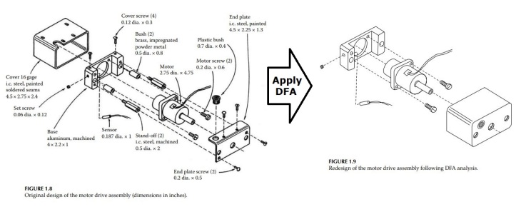
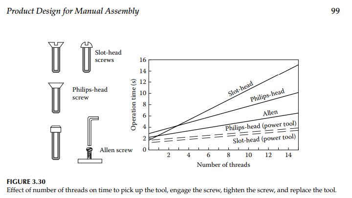
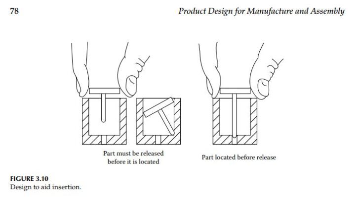
The focus of the book is to establish quantitative means of measuring the manufacturability and assemblability of a given product. It has tons of pictures and shows specific techniques to follow (and which to avoid) to reduce the assembly time, number of parts, and part cost. I’ll leave off with a couple shots from it.

[…] projects. Beginners learning to design for 3D printing (and even some veterans) would find his design tips document well worth the few minutes of reading […]
LikeLike
[…] projects. Beginners learning to design for 3D printing (and even some veterans) would find his design tips document well worth the few minutes of reading […]
LikeLike
[…] projects. Beginners learning to design for 3D printing (and even some veterans) would find his design tips document well worth the few minutes of reading […]
LikeLike
[…] projects. Beginners learning to design for 3D printing (and even some veterans) would find his design tips document well worth the few minutes of reading […]
LikeLike
[…] projects. Beginners learning to design for 3D printing (and even some veterans) would find his design tips document well worth the few minutes of reading […]
LikeLike
[…] projects. Beginners learning to design for 3D printing (and even some veterans) would find his design tips document well worth the few minutes of reading […]
LikeLike
[…] projects. Beginners learning to design for 3D printing (and even some veterans) would find his design tips document well worth the few minutes of reading […]
LikeLike
[…] projects. Beginners learning to design for 3D printing (and even some veterans) would find his design tips document well worth the few minutes of reading […]
LikeLike
[…] projects. Beginners learning to design for 3D printing (and even some veterans) would find his design tips document well worth the few minutes of reading […]
LikeLike
[…] projects. Beginners learning to design for 3D printing (and even some veterans) would find his design tips document well worth the few minutes of reading […]
LikeLike
[…] in May I wrote an article mentioning my entry into the 2018 Hackday Prize, and guess what? It won the first round along […]
LikeLike
[…] users out from making mistakes when possible with physical & digital poka-yoke. Balance empowering the user with control against disempowering them by limiting interactions to […]
LikeLike