One of my projects this summer has been analyzing the mechanical properties of 3D printed parts using a homemade testing machine. I’ve been trying to figure out how to optimize the printer settings to maximize the physical strength of parts while minimizing the plastic needed to make them.
As simple as smashing a few pieces of plastic sounds, I’ve had to face a fair amount of challenges on this little project. There’s a reason for the general lack of test data on this topic. It’s not just a matter of sitting down and pumping it out, but rather spending a lot of time redoing tests and staring at graphs that don’t make sense.
In this post I want to discuss some of the challenges I’ve encountered and share the results I’ve been able to produce so far, including what I now consider to be the best infill pattern.
Here’s the quick recap of the experimental test setup:
- All specimens were 3D printed on my FDM type Reprap PrintrBot, using Slic3r and Repetier Host software.
- All specimens were made of ABS filament from the same roll.
- All tests were run in a static 4 point bend configuration using TestrBot.
- Three of each specimen were used for each variable tested.
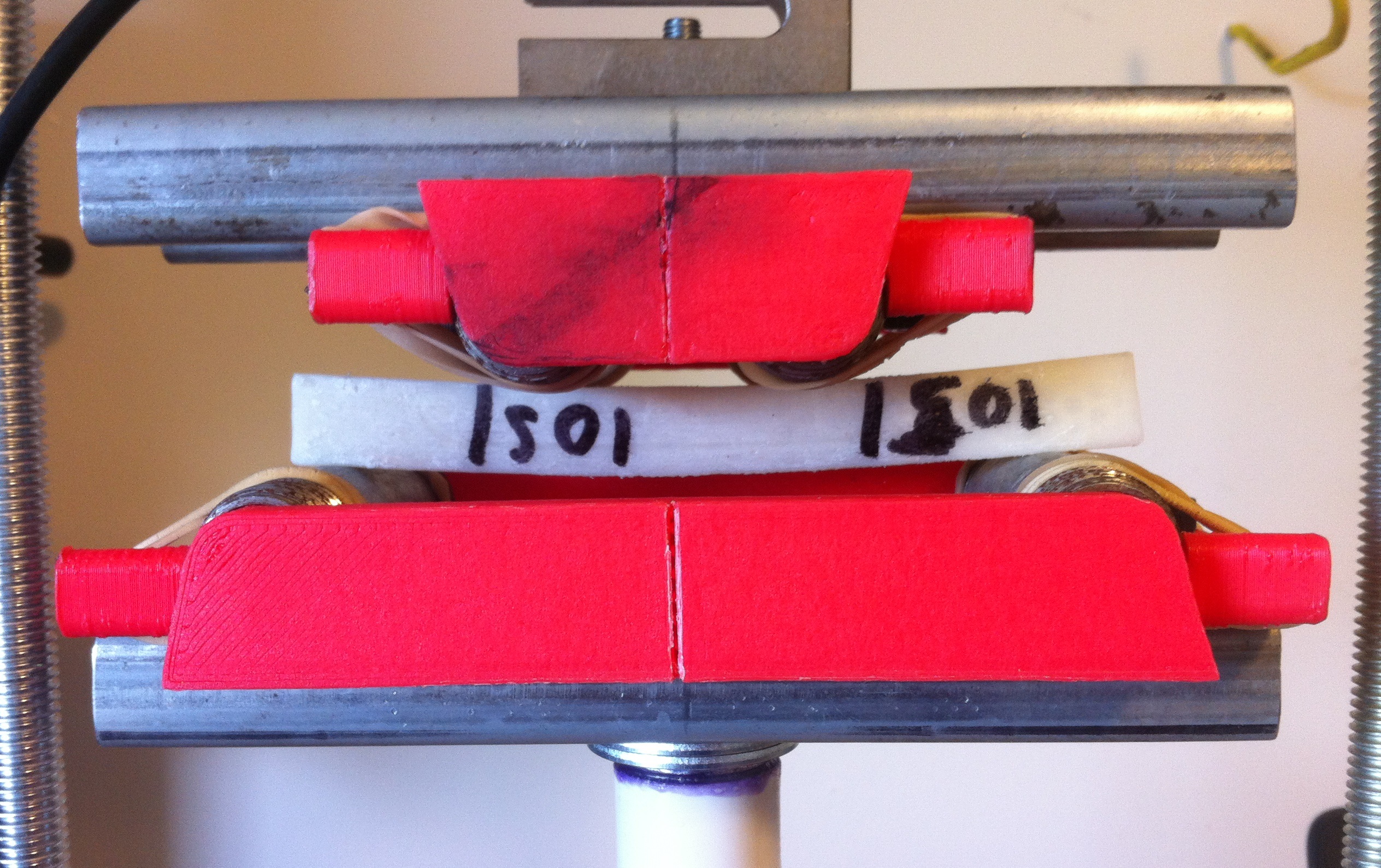
A white 3D printed specimen with awful hand writing on it.
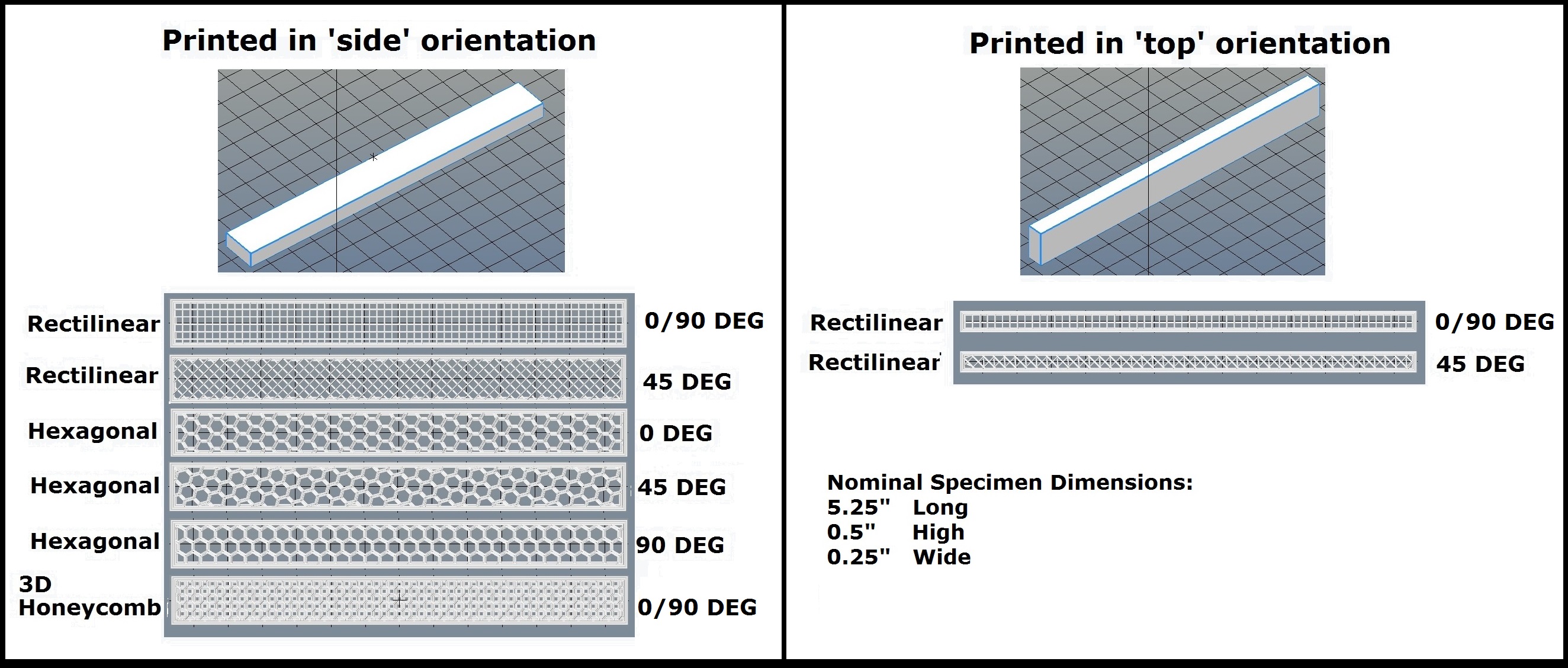
Parts were printed with different infill patterns and orientations to determine their strong and weak axes.
Testing Challenges:
For science to work properly I had to double check that my results were actually caused by the variable I was trying to test rather than by something else that interfered. And there were many potential sources of unintended interference:
Artifacts of Software Processing Magic: The programs I use to prepare my 3D models for printing are good, but they aren’t perfect. There’s a lot going on behind the scenes in this software and there are many seemingly innocuous settings that can have huge effects on the printed part.
One example I encountered was that playing with the extrusion width can greatly affect the mass and relative strength of the finished part, even while keeping all other settings constant. The crazy thing is that this effect is completely unpredictable! Try to find a pattern in this fancy pants graph.
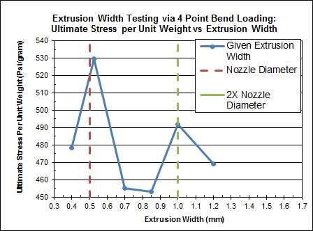
Ya know, maybe I’ll just leave the extrusion width settings at their default values.
Artifacts of Physical Manufacturing: My 3D printer is home built and has its own unique set of quirks (by which I mean I have to hit it sometimes). One of the biggest concerns here was the need to be aware of minute printing imperfections and even subtle amounts of warping. Any warping could cause the specimen to fall over prematurely, rather than break, resulting in a lower ultimate load. Testing three specimens per variable helps weed out outliers, unless of course your printer messes up three times in a row!
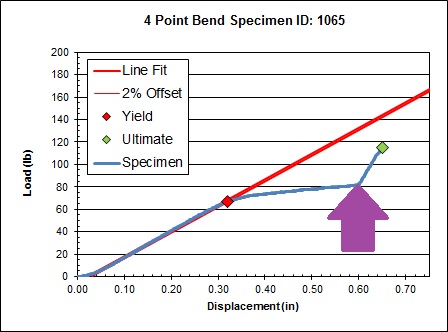
Artifacts of Testing: Human interference, changing ambient environment, and test fixture instability can all become the cause for a bad test run. In the example below the specimen yielded so much that it eventually came into contact with a screw on the test fixture, causing the load to spike. All data beyond the purple arrow is useless.
Results and Recommendations:
Despite the above challenges I was able to run enough good tests to confidently make some reasonable evidence based conclusions. These are my recommendations for maximizing the strength of 3D printed parts:
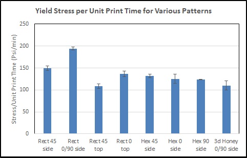
- The rectilinear infill pattern is the most efficient use of plastic and it also prints at the fastest rate! (The first part was unexpected!) The other two most useful infill patterns, hexagonal and 3D honeycomb, were slightly weaker in terms of yield stress per unit weight of plastic used. They also took 30% longer to print than rectilinear.
The primary problem with the hex and honeycomb patterns is their inefficient use of plastic infill near inside walls and their asymmetrical lattice structures. The dimensions of the combs are determined by the percent infill you choose rather than as a function of the space they are trying to fill. The result is that they don’t fit evenly into the shape and one side ends up being weaker.
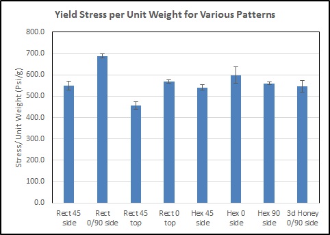 Yes I reported units in American Standard AND Metric. The absolute values don’t matter here, all I’m try to do is compare them relative to each other.
- To maximize the strength of prints for specific applications, orient your infill pattern to be normal to applied bending loads, and at 45 degrees from applied tensile loads.
- Printing the specimens from the ‘top’ orientation was a loss all around. The resulting failure mode was a delamination of the outer layers. (Note that if I had printed these specimens oriented vertically their bending strength would undoubtedly have been much worse.)
The lesson here is that both the load orientation and print orientation have a significant effect on the strength of FDM 3D printed parts.

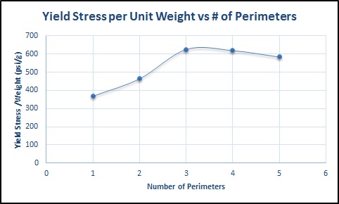
- Always print parts with 3 perimeters on all sides. The overall quality and print strength is greatly increased by having more than one perimeter, but the returns diminish soon after for multiple perimeters. (The exact diminishing rate will vary based on the part geometry & dimensions.)
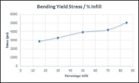
- The strength of materials as a function of infill percentage can be adequately approximated as a linear relationship. I saw no diminished return in strength no matter how much plastic you use.
UPDATE 2-8-16:
I decided to re-evaluate the above conclusion when I noticed that even though the graph was linear its slope was less than 1. That means I DID observe a reduced effectiveness for adding additional material… Doing some more research on testing done by others I determined that linear 1:1 scaling estimates work well with tensile stress, but not with bending.
What I mean to say is that under tensile stress a part with 50% infill will be 50% as strong as that part with 100% infill. BUT under bending stress that same part will be more than 50% as strong.
The reason is that bending stiffness is mostly a function of extreme fibers. (Remember: Stress = Mc/I?). Adding more material near the center of the part provides very little additional strength in bending applications.
- And finally, my earlier experiments showed that acetone vapor treatment reduces the strength of ABS plastic parts by a measurable amount; for me it was almost 20 % under bending loads.
.
I’m happy with the progress I’ve made so far. Not only has my cheap little testing machine proven adequate for my needs, but I’ve recently become aware of two separate individuals who are attempting to build their own TestrBot to continue this line of work!
There’s a lot I’m still curious about and I’m not done with the work I started here. But for now I need to take a break from testing so I can focus on an upcoming electric vehicle project. 🙂 (You all know how I feel about electric vehicles.)

Please forgive me where I don’t know much about 3D printers, but I find this technology to be nothing less than amazing! I was ,however, able to invest in some related stocks. Fingers crossed!!
LikeLike
Ha ha, good luck!!
LikeLiked by 1 person
[…] and it feels super strong in my hands! But how scientifically quantifiable is that? Take a look at my mechanical test results here to see how this infill compares to the traditional […]
LikeLike
Most excellent post and not just talk (tested with real samples!). If you have some time in the near future, perhaps testing MatterControls Optimized Hexagon infill will perform better than the Slic3r similar hexagon infill. Or not.
LikeLiked by 1 person
Thanks! And yes that does make me wonder. Ive never used matercontrols before so ill look into it
LikeLike
Great work! I had honestly thought at the start the 3d honeycomb would win out… so rectilinear infill pattern should be used for the majority of basic prints?
I am curious if you derived any specific conclusions about how the relation of infill type and density relate to bending loads or flexibility of a part?
LikeLike
Thanks! I originally thought that the honeycomb structures would be optimal too! But yes, based on my limited testing and some done by others, the rectilinear should be your go-to setting.
Regarding the infill density Ive concluded that a linear 1:1 strength derating is the best way to account for it. Meaning a part that has say 60% infill should be 60% as strong (meaning ultimate load) as if it was solid.
LikeLike
Thanks for taking the time to do such tests. So I understand that you recommend the rectilinear infill pattern with a fill density of 60% to get the best in terms of strength and material used and not the 3D Honeycomb? Do you recommend this setting also for printing parts for a 3d printer using PLA?
LikeLike
Yes on the rectilinear pattern, but no on the density. The % infill that you use should vary based on how strong you need the parts to be. My testing showed that you get what you pay for in terms of plastic used to strength gained.
If you use X% infill then the printed part will be X% as strong as if it had 100% infill. (That said, I almost never choose anything less that 10 or 15%.)
LikeLike
So if optimized based on model orientation, rectilinear will win out in strength tests atleast when bent in that specific direction.
However in theory the 3d honeycomb pattern would show more consistent strength when bent in any direction without having to optimize print orientation.
Am I understanding this right?
LikeLike
What layer height are you working at? I would think it would have as much of an impact. Probably a function of the Width * Height would come up with the optimal print.
LikeLiked by 1 person
My layer height was .3mm for all tests. You are right though, that is a significant variable. Testing the effect of layer height was performed by someone else at this link herehttp://my3dmatter.com/influence-infill-layer-height-pattern/
In summary, they tested between .1 and .4mm in PLA and observed an increase in strength with layer height up to .2mm, then no change in strength up to .4mm.
On a related note, the extruder nozzle diameter is also important, and other research Ive read showed larger nozzles producing stronger prints (my nozzle is .5mm).
LikeLike
I have been using Simplify3D to do some prints lately, S3D allows you to generate infill at more than one set of angles. For example, you can generate rectilinear infill at 45, 135, 0, and 90 degrees. I have found that I can dramatically reduce the instance of delamination between the perimeters and infill by doing just that, particularly on thin-walled, cylindrical shapes. I theorize that this pattern prevents there from being localized zones where the infill makes poor contact with the perimeter along the entire height of the print.
LikeLike
I believe triangles would be even better than rectangles for structural strength, consider how bridges are designed. And extending that idea to 3 dimensions, tetrahedrons would be even better. I’m not sure how this would be accomplished and I have not found any software that will fill with Tetrahedrons, so it may not be practical.
LikeLike
Hi! Nice data! By chance, do you also have data on rigidity (brittleness)? Right now, I’m interested on how to maximize rigidity of my printout. That is, choose one that bends as little as possible under applied force. The strength is not important, as long as it is decent…
LikeLike
Thanks Deep! For rigidity you want a material with a high young’s modulus. (Or a low ‘% elongation at break’) Quick answer is PLA if you have consumer grade machine. Data per here: http://bit.ly/2gKG069
And of course maximize part stiffness with good design & by printing solid.
This also might also be a useful quick reference, a chart of printing material properties (by esun): http://bit.ly/2jyHmQM
LikeLike
Thank you for your awesome work. Would you consider updating your study with the cubic infill pattern the default pattern for Slic3r.
LikeLike
Glad you like it! More testing is on my to-do list of considerations, I also wanted to test the triangular infill pattern too. But at this moment my focus is on finishing development of the latest thing, an educational sumo robot kit!
LikeLike
Nice article. I don’t understand the “you get what you pay for” idea in terms of plastic used. If an I-beam is stiffer than a solid beam, it should be possible to make a plastic lattice configuration that is stiffer than a solid configuration, right? Or is my materials understanding woefully lacking and there is some chemical reason an I-beam is stiffer than a solid beam?
LikeLike
HI Matt, finally catching up on comments here! 🙂
All I meant by ‘you get what you pay for’ is that using more plastic stronger parts at a 1:1 proportion.
No I do not believe that any possible latice configuration will be stiffer than a solid infill of the same material.
Regarding the I beam comment, it has everything to do with geometry and nothing to do with material. You might find this article interesting, it describes the properties & relative merits of different beam section geometries. https://engineerdog.com/2014/11/17/free-resource-strength-of-materials-made-easy/
LikeLike
Excellent work! I plan to make my own TestrBot soon to test out my own 3D printed parts!
As a fellow mechanical engineer, I hope you don’t mind if I offer some suggestions for improvement, should you wish to continue this effort in the future:
1. Reference the test procedure you are following. I’m assuming you’re using ASTM D6272 “Standard Test Method for Flexural Properties of Plastics by Four-Point Bending” or similar. Note that this procedure requires at least 5 specimens per condition, so you’re a bit light with only 3.
2. Perform an analysis of variance (ANOVA) to determine if the differences you observed are actually statistically significant.
Keep up the great work!
LikeLiked by 1 person
Good feedback thanks Tim! My testing series is not what I would consider ‘rigorous’. More like, ‘scientific enough to satisfy my curiosity’ for the time being. 🙂
At this time I don’t have plans to continue this line of testing although I am developing a project along a tangential path using similar pieces of this puzzle.
If you are planning a build then I should point out that if I were to do it again there are things I would do differently.
Primarily, the 200 lb max load is extremely limiting for material testing applications. I was lucky that my tests could be adequately conducted via a 4 point bend with
<200 lbs. (Forget about tensile testing!) (You can't always scale the specimen size down to suit the machine without introducing undesirable variables into the system. As it was I couldn't test PLA printed above ~60% infill.)
Second, that the Testrbot prioritized minimal cost at the expense of everything else. Usability, appearance, load capacity, etc. The design in its current
form cannot be scaled up much beyond 200 lb without running into
problems with the arduino resolution & load capacity of the 3D printed
parts. I would use an off the self data acquisition module & linear
actuator with integrated potentiometer next time around.
LikeLike
Thanks for the caveats! I agree that the 200 lbf capability is really too low to perform much useful testing of 3D printed polymer specimens, however it is still a great project, and for the particular application I have in mind this is ideal. I have several Z Corp plaster binder jetting printers, and am planning to develop new powder and binder options. This little tester will be perfect for evaluating the green strength of the parts!
I think an inexpensive open source UTS machine is something that would be extremely useful, helping to further democratizing science and research. For a higher capacity machine, I found a few existing options out there that might be a good place to start. There’s a couple pseudo opensource test machines out there, but your costs an order of magnitude less, which is quite impressive!
LikeLiked by 1 person
Thanks again Tim! I had not heard of either of those but the openLETT looks very similar to the concept I imagined if I were to try this again. 2800 isnt a bad deal especially if it has custom software but i think beating that is easily doable.
Actually I would be interested in building up my own version of that at some point but Im too profit motivated to do a big machine for no reason. Democratizing science sounds like a great cause but it doesn’t feel like there is enough public interest/need to me. I see test machines as niche tools only of interest to very few people. And of those people who care enough and would know how to use a UTS most are institutional anyway and are already served by the existing (really expensive) brand name products.
If you do decide to move forward on your project Id be interested to hear how it goes. Feel free to send me a PM @ MechEngineerMike@gmail.com if you want to bounce ideas off someone.
LikeLike
Thanks Mike! I totally understand the profit motive, however I would mention that there are now several open hardware business models that seem to be doing well, so the two aren’t necessarily mutually exclusive. 🙂
I agree that a UTS is a niche tool, but I think the potential user base is increasing. With the advent of 3D printing, many more people now have the ability to make their own materials and tailor their properties (and easily make test specimens); I know that I previously had no use for a UTS, but now I can think of all sorts of uses I could put it to. I think a large part of what’s keeping it niche is that the machines are still so expensive; not many people were buying 3D printers either when they were tens of thousands of dollars.
Will definitely take you up on your offer to bounce ideas off of; that’s always useful!
LikeLike
Hi Michael – Thanks for doing this testing! Could you tell us what the infill percentage was for your comparisons of infill patterns??
LikeLike
Outstanding writeup. Just one thing, don’t you mean areas to the RIGHT of the purple arrow are useless (i.e. where displacement increases past the point of unintended machine contact)
LikeLike
Thanks! Yes that is what I meant
LikeLike
I think your results are only applicable to printing cubes and similar flat sided shapes. The 90 deg rectilinear nicely hits all the 90 deg walls and because of that has that even force distribution you mention honeycomb is lacking. But how would a hemisphere compare with that same infill?
I know you’re not planning on doing more testing, but just something else for people to keep in mind when choosing infills.
LikeLike
I know it’s been 7 years now, but….any way to get the raw data for any/all of these charts?
While plotting something like stress per wt vs extrusion width is good for trying to compare ‘efficiency’, it’d be nice to see stress vs extrusion width and also wt vs extrusion width. Cause, maybe someone’s goal is less to get the most strength out of the least material, but just to get more strength (so stress vs extrusion width without using weight to try to ‘normalize’ would be the thing to look it). It’d also be interesting to see the trend of how extrusion width impacted final weight.
Thx
LikeLike
HI, sorry that was a couple computers ago and its been lost to time
LikeLike
Looking through this, it seems all the prints tested have some rather severe under-extrusion taking place. It would be interesting to see how these test results change when using modern slicers and modern printers.
LikeLike
Agreed, things have come a long way since then. But there have been others who have run these kinds of tests too, ‘cnc kitchen’ comes to mind
LikeLike