Everyone who has ever 3D printed something has faced the same problem: How to make parts as strong as possible while consuming as little material as you can get away with?
3D printed objects are typically not 100% solid and are instead held together by a lattice structure that uses some amount less than that. Printing at higher infill densities will of course make your object stronger, but at the cost of more materials, longer printing times, and reduced effectiveness of the additional material used.
The specific infill pattern you use will have a huge effect on the strength of the finished part. As of right now I can choose from a total of 7 different infill patterns, only 3 of which are actually practical (Concentric, Honeycomb, and Rectilinear). There are other infill patterns available for people using Makerbot software (which allows you to make custom designs like ‘cat-fill’), but those patterns are a novelty more than anything else.

If you’ll notice, all patterns currently available simply repeat themselves every layer. The infill designs are all ‘Z-axis independent structures’. This causes finished parts to have a mechanical strength that differs depending on which axis is under load (an undesirable characteristic). Very soon this will no longer be the case.
.
A friend and I recognized the limits of current infill patterns and decided to design our own. Knowing that a hexagonal structure uses the least material to create a lattice of cells within a given volume, we let our design take inspiration from the way that bee’s nests intersect two opposing honeycomb layers into each other:
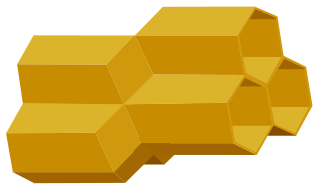
Here is the result of our work:
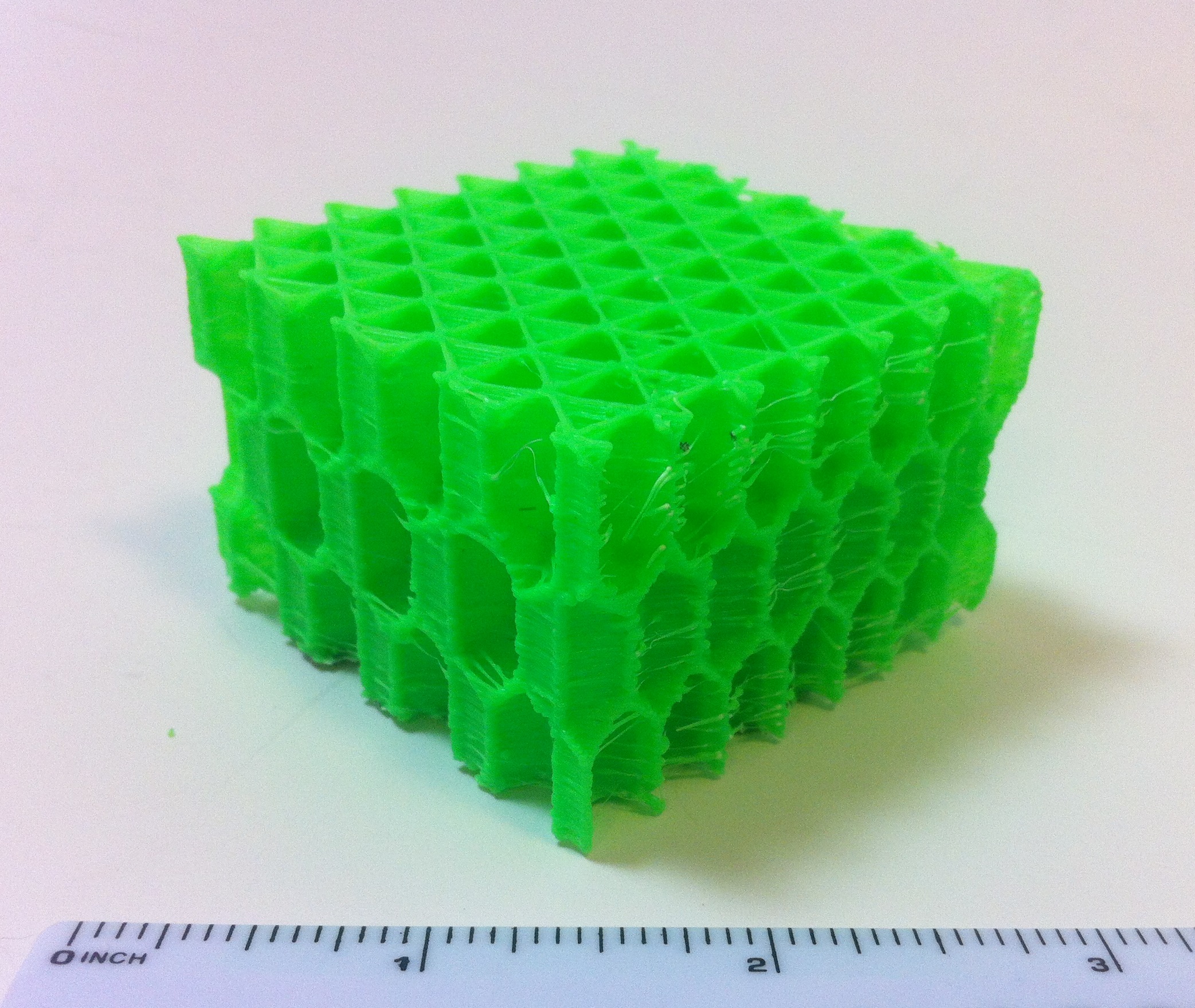
For a 3D view see: http://www.thingiverse.com/thing:714679
Cool huh? Unfortunately we designed this the hard way, by literally drawing a cube and subtracting out the honeycomb shapes to leave behind the appropriate wall thickness throughout, then printing the object as 100% solid. This object took 2 hours to slice, (a process that usually only takes moments) and 4 hours to print. It is definitely not optimal in that way, but it was only intended as a concept. The result actually feels very strong for its weight and I was able to stand on this thing without issue.
What we didn’t realize until later was that people have been working on and talking about designs like this for years. In fact, the good folk(s) at Slic3r were already hard at work adding a Z-dependent lattice structure into their slicing software!
The next official version of Slic3r hasn’t been released yet, but you can download the experimental version and try out their 3D Honeycomb design, which looks like this:
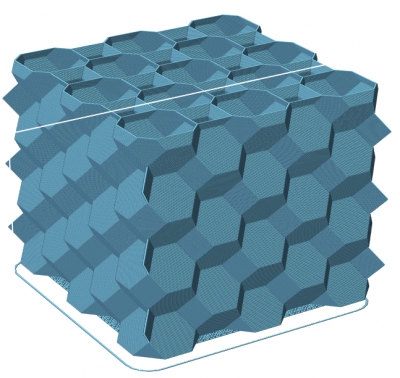
This new infill pattern should, in theory, provide maximum strength in all axes while using the least amount of material to do so. Obviously, I’m really looking forward to the next official release of Slic3r!
Final Note: I also didn’t realize until today that Slic3r is almost entirely a one man job! Made by Alessandro Ranellucci, a software designer from Italy. I love this free software so I decided to buy this man a beer via his donation page; you are welcome to do the same.
Update: 7-24-15
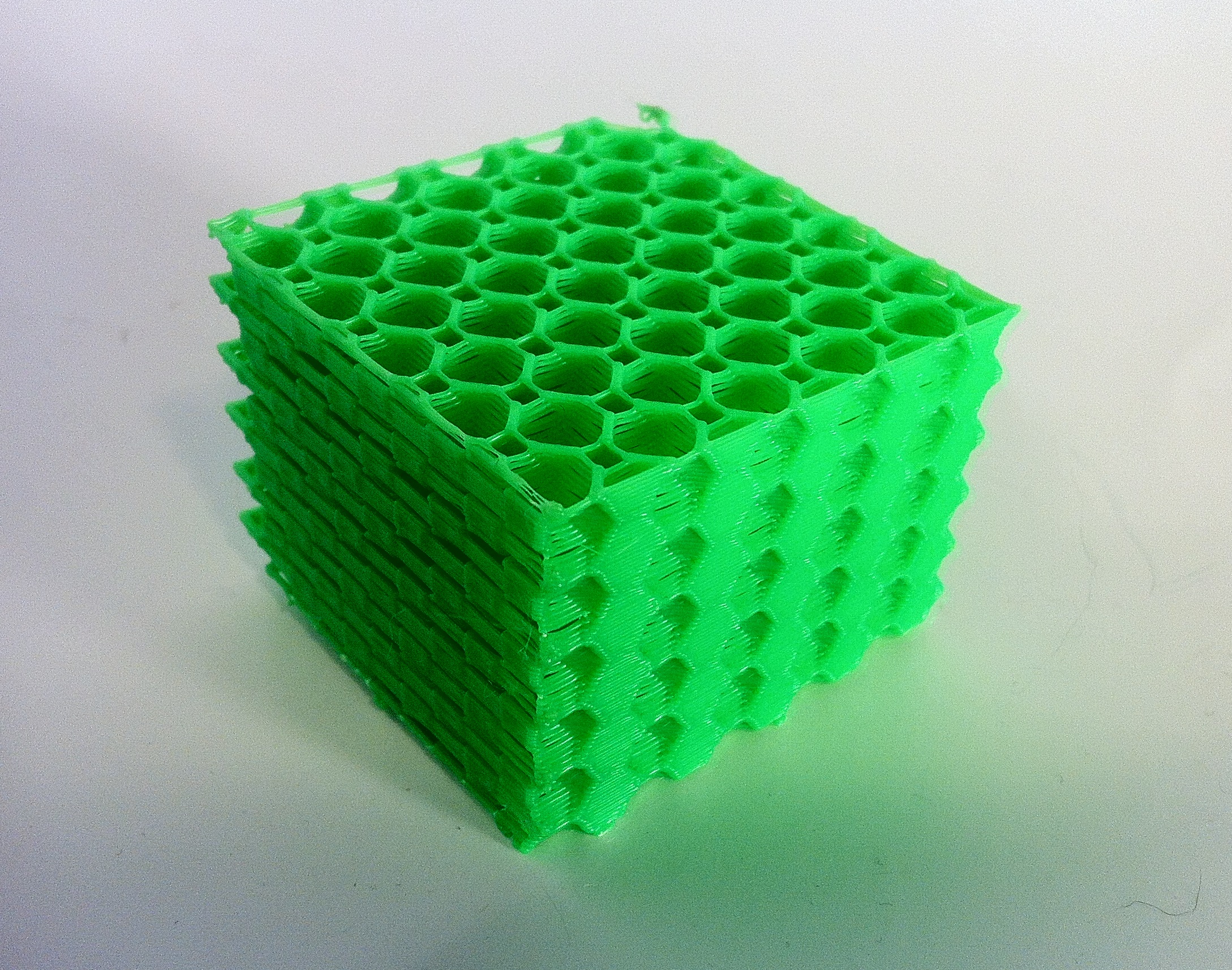
Slic3r recently released it’s new version 1.2.9 which has more capabilities than I currently know how to use! The most obvious one is the new 3D honeycomb infill, which looks fantastic! I printed out an example block with no exterior walls to provide a visual comparison to my infill design.
This little cube is only 20% infill and it feels super strong in my hands! But how scientifically quantifiable is that? Take a look at my mechanical test results here to see how this infill compares to the traditional options!

No direct experience (yet) with 3D printing, and on top of that, I didn’t exactly fully conceptualize what your design was…. In the green structure, it seems it’s triangles on two sides and oddly extended hexagons on the other, while in your 3D rendering, well… there’s not enough of it but I don’t see how it can be cross-cut to produce the triangles, at the very least. The slic3r model seems interesting, but I’d love to know how much strength it has on a given axis compared to patterns that are straight along that axis. How do you typically measure infill patterns (to get an accurate read)? Do you put measured weights on top? One of those “smashers” like they use in the industry? Or maybe the tightening of a clamp?
LikeLiked by 1 person
*The front right side view of the green print gives the best explanation of what it is. The other sides have funny cross sections because of where I cut the cube model (so we could see inside). The triangles are the result of a simpler to model approximation of the actual ends of the combs. You can get a 3d view of the model here: http://www.thingiverse.com/thing:714679
*As to your question regarding testing, ha ha Scott you ask the exact right thing! The answer is that very little quality mechanical testing has been done to analyse these shapes in 3d printed objects. This has been the subject of a big project of mine and a series I will be posting about in the following weeks!
LikeLiked by 1 person
[…] ability to accurately predict reality because they cannot consider artifacts of manufacturing or complicated internal specimen geometry. These are significant drawbacks especially considering that the most common type of consumer grade […]
LikeLike
Hi! I just found this article via a Reddit link. Thank you very much, and if you have ideas… share them 🙂
LikeLiked by 1 person
Oh, I used the wrong profile for posting. Slic3r author here. 🙂
LikeLiked by 2 people
The new version is working great for me, keep up the good work!
LikeLike
How do you calculate infill-density? I mean, I can tell that 18% is more dense than 14% infill, but what makes it 18% and 14% and not say, 9% and 7% ?
LikeLike
Hi Sauvik, the exact toolpath & number of passes per layer that defines a given infill % is calculated within the slicing program and is invisible to the end user. My best guess is that when I select 20% infill it calculates the surface area of the entire layer (excluding all perimeters) and then divides that by the selected extrusion width to find the total length to extrude on that layer. Then it uses proportions to scale the selected infill pattern so that it distributes that exact length.
LikeLike
What about rotating the hexagonal pattern each layer half the thickness of the wall thickness so they spiral.
LikeLike
My guess is that that would mimic the negative aspects of the 3D honeycomb structure without the desired benefit. Shifting the pattern off the lower layer reduces the bonded surface area between the layers. Imagining printing a tower containing a single honeycomb cell, comparing a spiral column under load vs a straight walled column and I cant imagine that the spiral has any advantages in bending, buckling, or tension.
LikeLike
I would have thought that because you are rotating the points touching the outer skin (wall) you are creating more points of contact with it hence spreading the load.
LikeLike
Are you able to adjust the heat at the nozzle for different materials used as the resin.? If so, what are the low temperatures and high tempetatures .?
LikeLike
[…] the one hand, if you are looking for a strong infill, you can choose Grid, Triangular, and Solid Honeycomb infill patterns. On the other hand, Rectilinear and Fast Honeycomb may exchange for faster printing […]
LikeLike